
Crystal Oscillator vs Piezo Crystal Unit: A Comparative Selection Guide for Smart Manufacturing
Crystal Oscillator vs Piezo Crystal Unit: A Comparative Selection Guide for Smart Manufacturing
A factory automation system uses frequency control in almost every synchronized action: motor drives, robot controllers, vision triggers, industrial gateways, and safety networks. Designers often ask whether to specify a crystal oscillator or a piezoelectric crystal component such as a piezo crystal unit or crystal resonator. The short answer is that a crystal oscillator is an active, ready-to-output clock module, while a piezo crystal unit is a passive frequency element that must be driven by an oscillator circuit on the host IC. The choice is therefore an architecture and constraint decision rather than a simple part-number preference.
Selection principle: Choose a crystal oscillator when the design needs a complete clock module with defined supply-voltage and temperature behavior. Choose a piezo crystal unit or resonator when the host IC already contains an oscillator circuit and the system can tolerate the added design work of setting load capacitance and validating the external oscillation loop.
Why This Oscillator vs Piezo Crystal Unit Decision Matters
In smart manufacturing, the difference between active crystal oscillators and passive piezo crystal components affects every layer of the electronics bill of materials. A PLC, servo drive, industrial camera, edge computer, or wireless sensor node must generate a trustworthy clock for data sampling, protocol timing, and motion synchronization. If the selected architecture cannot maintain frequency under the equipment temperature envelope, the system may still work on the bench and fail after installation beside a hot motor drive or inside a sealed control cabinet.
Procurement teams also need clarity because oscillators and piezo crystal units often share the same quartz-based technology. They are not competing quality levels; they are different component architectures. The comparison below covers component families, not supplier rankings. It uses verified product records for quartz crystal oscillators and piezoelectric crystal components to explain when one architecture deserves a place in a manufacturing BOM.
Industry Context: Timing Components in Smart Manufacturing
Smart manufacturing equipment sits at the intersection of networking, industrial control, automotive electronics, instrumentation, communication devices, and consumer-oriented connected products. The global importance of this category is visible in market data. According to MarketsandMarkets, the global crystal oscillator market was valued at approximately USD 2.89 billion in 2025 and is projected to reach USD 3.66 billion by 2030. Precedence Research reports that the Asia-Pacific region dominates the crystal oscillator market, capturing more than 42% of the market in 2024 because of high electronics production in China, Japan, and South Korea.
Those figures describe oscillators specifically, but the underlying quartz timing ecosystem is broader. Piezoelectric crystal components, piezo elements, piezo crystal units, quartz crystal resonators, crystal filters, and SAW crystal resonators are also part of the same design vocabulary. The shared quartz advantage is frequency accuracy and temperature repeatability. The difference from an oscillator appears after the quartz wafer is packaged: an oscillator adds an active circuit, while a resonator or crystal unit remains a passive frequency element.
Component Definitions: Crystal Oscillator vs Piezo Crystal Unit
Quartz Crystal Oscillator
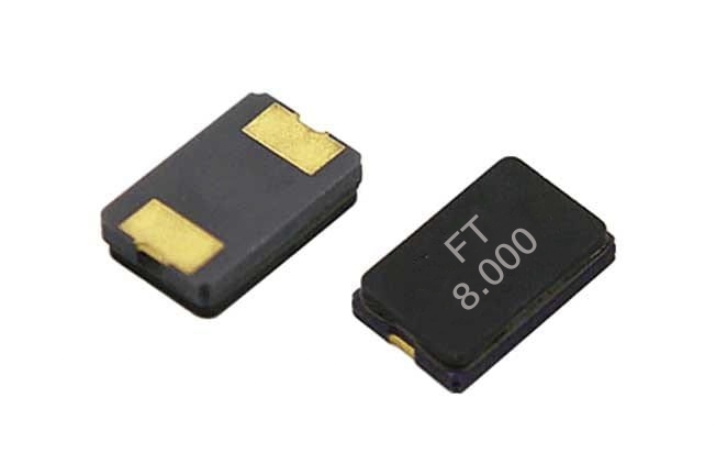
A quartz crystal oscillator, sometimes called an active crystal oscillator or clock oscillator, contains a quartz wafer plus an active circuit that produces an electrical output signal. In the product record used for this guide, the oscillator family comes in SMD package sizes 2.0 x 1.6 mm, 3.2 x 2.5 mm, and 5.0 x 3.2 mm, commonly labeled as 2016, 3225, and 5032. The nominal frequency covers 32.768 kHz and 1.5 MHz to 50 MHz. Supply voltage options are 1.8 V to 3.3 V and 3.3 V to 5.0 V. The data sheet states temperature-related stability of ±20 ppm from -20°C to +70°C and ±25 ppm from -40°C to +85°C. Construction materials recorded for this oscillator family include SiO2, silver, gold, and a metal iron shell.
Piezoelectric Crystal Component / Piezo Crystal Unit
Piezo elements and piezo crystal units are frequency-determining components that rely on an external oscillator circuit to generate the final clock. The reviewed product category includes crystal resonators, crystal filters, and SAW crystal resonators. Its nominal frequency range is 1 MHz to 96 MHz. Load capacitance is specified as 4 pF to 33 pF. Frequency tolerance is ±5 ppm to ±100 ppm, and frequency stability is ±10 ppm to ±100 ppm. The operating temperature range is -55°C to +125°C. Package sizes span SMD7050, SMD6035, SMD5032, SMD3225, SMD2520, SMD2016, and SMD1612. Material construction is recorded as metal cover, ceramic base, and quartz wafer.
In application notes, this passive component family is matched with oscillator circuits to provide a stable clock signal for an IC. Reported use environments include high-temperature working conditions and vibration operation. Typical products include mobile devices, Bluetooth headsets, smart air conditioners, security cameras, smart home appliances, and communication electronics.
Architecture Differences That Affect Smart Manufacturing Designs
Integration Complexity
Crystal oscillators are designed to simplify system integration. The oscillator circuit is built inside the module, so the output from the oscillator can be connected directly to a clock input or logic device. The designer does not need to calculate the optimum load capacitance for a bare quartz crystal or tune the negative resistance of the oscillator stage.
Piezo crystal units impose a different integration workload. Because the component is passive, the MCU, SoC, or radio IC must provide an on-chip oscillator circuit. The board designer must match the load capacitance requirement and verify that the IC can start up reliably across process, voltage, and temperature. If the load capacitance is incorrect, the real operating frequency can shift away from the nominal value printed on the label.
Environmental Tolerance
The reviewed oscillator data covers two operating windows: -20°C to +70°C at ±20 ppm and -40°C to +85°C at ±25 ppm. The reviewed piezo crystal component family covers a wider recorded temperature range of -55°C to +125°C, while its element-level stability is ±10 ppm to ±100 ppm.
That wider temperature range does not automatically mean a piezo crystal unit is easier to use. The external IC oscillator circuit must also support the low and high temperature extremes. However, when the system specification includes -55°C operation, a passive quartz crystal unit plus a properly designed external oscillator is often a more practical starting point than assuming a standard SMD oscillator module will survive outside its documented temperature range.
BOM and Design Risk
From a procurement point of view, a crystal oscillator consolidates more function into one component. It can reduce procurement line items and simplify board bring-up. A piezo crystal unit may be a smaller BOM line, but it creates hidden design work in the form of oscillator circuit validation. High-volume production lines should weigh the cost of that engineering validation against the unit-cost difference between a complete oscillator and a bare crystal element.
Use Cases in Smart Manufacturing
Control Boards, HMI, and Vision Systems
For industrial control boards, HMI panels, protocol converters, and vision controllers, designers usually need a clock source that works as soon as power is applied. An SMD crystal oscillator in a 5032 or 3225 package is a straightforward option, especially when the board runs from a 3.3 V or 5.0 V rail. The oscillator data sheet already defines output stability over the board temperature range, which shortens system-level validation.
Smart Meters and Industrial Sensing
Documented production data for piezo crystal components used in smart meters shows sustained shipments of five million units over ten years, with stable operation and a three-to-four-week delivery cycle for the customized frequency and packaging used in that program. For utility metering and industrial sensing, this demonstrates that high-volume deployment depends not only on the crystal element itself but also on the ability to customize packaging and frequency while preserving production continuity.
Bluetooth Modules and Wireless Sensor Nodes
For low-power wireless communication modules, Bluetooth devices, and small sensor nodes, a small piezo crystal unit in a 2016 or 1612 package can help save PCB area. The application unit for piezoelectric crystal components explicitly lists Bluetooth devices and communication electronics. The function is to provide a stable clock signal to the IC while keeping the mechanical footprint compatible with compact product designs.
Comparison Table: Crystal Oscillator vs Piezo Crystal Unit
| Dimension | Crystal Oscillator | Piezo Crystal Unit / Resonator |
|---|---|---|
| Architecture | Active frequency module with integrated oscillation circuit | Passive quartz/ceramic frequency element used with host IC oscillator circuit |
| Representative family | OSC-SMD2016 / OSC-SMD3225 / OSC-SMD5032 | SMD7050 / 6035 / 5032 / 3225 / 2520 / 2016 / 1612 |
| Nominal frequency range | 32.768 kHz; 1.5 MHz to 50 MHz | 1 MHz to 96 MHz |
| Load capacitance | No external load capacitance matching required from the oscillator data sheet | 4 pF to 33 pF |
| Frequency tolerance / stability | ±20 ppm from -20°C to +70°C; ±25 ppm from -40°C to +85°C | Tolerance ±5 ppm to ±100 ppm; stability ±10 ppm to ±100 ppm |
| Operating temperature | -20°C to +70°C and -40°C to +85°C windows | -55°C to +125°C |
| Supply voltage | 1.8 V to 3.3 V; 3.3 V to 5.0 V | Typically defined by the external IC oscillator circuit |
| Construction | SiO2, silver, gold, metal iron shell | Metal cover, ceramic base, quartz wafer |
| Integration complexity | Lower: one module produces a clock output | Higher: external oscillator circuit and load capacitance must be validated |
| Typical applications | Communication, automotive, consumer electronics | Smart home appliances, communication electronics, Bluetooth devices |
Step-by-Step Selection Breakdown
Step 1: Define the Required Frequency and Stability
List the nominal frequency needed by the MCU, SoC, radio, or communication interface. If the frequency is inside 1 MHz to 96 MHz, both architecture families may be viable. If the circuit needs 32.768 kHz, an oscillator family that specifically covers 32.768 kHz and 1.5 MHz to 50 MHz is one available path.
Step 2: Map the Operating Temperature Envelope
Determine whether the final product must survive -55°C, -40°C, +85°C, or +125°C. Compare those values with the oscillator data sheet windows and with the crystal component temperature range. The wider component temperature does not eliminate the need for a robust external oscillator circuit, but it narrows the mechanical choices.
Step 3: Check the Host IC Oscillator Capability
Read the MCU, Ethernet PHY, sensor bridge, or wireless transceiver datasheet. If it contains a working crystal-oscillator driver with gain margin and programmable load capacitance, a piezo crystal unit can be used. If the IC has no internal oscillator driver or if the clock circuit is already marginal, an active crystal oscillator is usually the safer integration path.
Step 4: Evaluate Load Capacitance and PCB Parasitics
When using a piezo crystal unit, calculate the two external load capacitors from the specified 4 pF to 33 pF range. Include PCB stray capacitance and IC pin capacitance in the calculation. For an oscillator module, this step is simplified because the data sheet focuses on supply voltage and output logic levels.
Step 5: Review Package Size and Layout
Select a package that can be assembled reliably on the production line. Oscillator packages in this review include 2016, 3225, and 5032. Piezo crystal components are available from 1612 to 7050. Smaller packages save board area but can create more sensitivity to layout parasitics.
Step 6: Confirm Compliance and Environmental Restrictions
For EU-bound assemblies, verify RoHS and REACH compliance. In automotive safety domains, confirm whether AEC-Q200 stress-test qualification applies to the oscillator. These constraints should be checked before the electrical design is finalized to avoid a later approval bottleneck.
Certification and Standards Constraints
Compliance is a core part of HVQ2 buying decisions. The reviewed product record for piezoelectric components includes an EU RoHS Compliance Certificate issued by SGS-CSTC Standards Technical Services Co., Ltd. Shenzhen Branch. The certificate number is SZXEC25001335806, issued on 2025-04-25, with scope covering SAW Resonator & Filter and SMD series. It references EU Directive (EU) 2015/863 amending Annex II to Directive 2011/65/EU. For buyers shipping into the EU, this is a useful due-diligence example of what a complete compliance file should contain.
For automotive smart-manufacturing systems, verified industry data states that automotive-grade crystal oscillators must comply with the AEC-Q200 stress test qualification for use in ADAS and safety-critical systems. If the component feeds into automotive production equipment or an automotive product itself, the supplier should show AEC-Q200 readiness rather than only a general environmental certificate.
Frequently Asked Questions
1. Which compliance checks matter when sourcing crystal oscillators and piezo crystal components?
For components going into EU equipment, verify environmental certificates. The reviewed RoHS certificate, issued by SGS-CSTC under EU Directive 2011/65/EU as amended by EU 2015/863, covers SAW resonators, filters, and SMD-series devices. For automotive safety systems, automotive-grade crystal oscillators should meet the AEC-Q200 stress-test qualification. REACH compliance is an additional requirement for many industrial buyers.
2. Which timing architecture is easier to integrate: oscillator or piezo crystal unit?
A quartz crystal oscillator is easier at board level because it is a complete active clock module. Once power, ground, and output are connected, a clock signal is available. A piezo crystal unit is passive; the host IC oscillator circuit must provide the drive and the correct load capacitance. If load capacitance is wrong, the real system frequency may shift away from the nominal value. This makes the oscillator the lower-risk layout choice when the IC has no internal oscillator circuit or no margin for external tuning.
3. What parameters should be checked first for high-volume production?
Start with nominal frequency coverage, load capacitance, frequency tolerance and stability, operating temperature, package size, and, for oscillator modules, supply voltage. The reviewed oscillator family covers 32.768 kHz and 1.5 MHz to 50 MHz. The reviewed piezo crystal component family covers 1 MHz to 96 MHz with SMD options from 1612 to 7050. After these parameters are locked, packaging and frequency customization can be reviewed. In a documented smart-meter program, five million piezo crystal components operated stably over ten years, with customized packaging and frequency, and a three-to-four-week delivery cycle.
4. How do operating temperatures affect architecture choice?
The reviewed oscillator specification lists -20°C to +70°C at ±20 ppm and -40°C to +85°C at ±25 ppm. The reviewed piezo crystal component family lists -55°C to +125°C with frequency stability of ±10 ppm to ±100 ppm. If the board is exposed to very low temperatures, the external oscillator circuit and the IC must operate to that point, not only the crystal unit. If the system cannot tolerate extra design burden but stays inside -40°C to +85°C, an active oscillator is a practical default.
5. What procurement plan moves from architecture choice to sample and mass production?
After choosing an architecture, define target frequency, effective load capacitance, package size, supply voltage, and temperature window. Require RoHS, REACH, and, if applicable, AEC-Q200 evidence. Validate a small batch through solder-in tests and frequency measurements at the high and low temperature limits. For manufacturers that support ODM customization, production lead time for custom parameters or appearance is usually 30 to 45 days, and minimum order quantities can be as low as 1,000 pieces. Budget should include engineering validation, not only unit price, because the passive piezo path requires more system bring-up effort.
Conclusion
For smart manufacturing, there is no universal winner between a crystal oscillator and a piezo crystal unit. An active oscillator gives the designer a self-contained clock source with defined supply voltage, output levels, and temperature stability. A piezo crystal unit gives the designer a smaller passive frequency element with a wider recorded temperature range, but it requires an external oscillator circuit and careful matching of load capacitance.
The best procurement outcome comes from mapping the system specification first. If integration speed matters and the environment stays within the oscillator data-sheet limits, an SMD oscillator is the lower-effort path. If the product requires extreme temperature tolerance, very small package size, or tight cost pressure at high volume, a piezo crystal unit should be evaluated beside the host IC oscillator capability.
For buyers building a checkable sourcing file, the practical evidence list is already available in this guide: verified frequency ranges, stability parameters, load capacitance, package options, operating temperature, RoHS certificate scope, AEC-Q200 relevance, and documented high-volume delivery performance.
Download the crystal oscillator and piezo crystal component brochure for specification verificationHave Questions or Need More Details?
Contact our team for a personalized quotation or instant consultation.
Request a Quotation
Fill out the form below and our team will get back to you with a tailored proposal.
WhatsApp Direct Chat
Prefer to chat in real-time? Message us on WhatsApp for instant assistance & quick answers.
- Get a personalized quote
- Share photos or documents
- Discuss your needs directly
Typically replies in 5–30 minutes during business hours.