
Technical Guide to Piezoelectric Crystal Unit Parameters for Advanced Oscillator Design in Industry 4.0
Oscillator accuracy in an Industry 4.0 line is not decided by the oscillator alone. It is decided by how the parameters of the piezoelectric crystal unit — load capacitance, equivalent series resistance, frequency tolerance, frequency stability and operating temperature range — line up with the oscillator circuit around it. This guide explains those parameters one by one, shows how they interact inside a real timing loop, and gives design and procurement teams a repeatable way to specify them for automated manufacturing equipment.
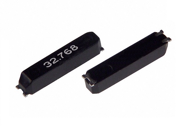
Problem Definition: Why Crystal Parameters Approved in the Lab Fail on the Production Line
A timing design usually starts on a bench, at room temperature, with a single prototype board. It ends on a line where cabinets run warm, motors introduce vibration, and hundreds of units are built in a single batch. Those two environments do not test the same thing. A crystal unit that holds frequency on the bench can still push an oscillator outside its tolerance window once temperature, drive level and circuit load capacitance all shift together.
The failure is rarely a single bad component. It is a specification gap. Three situations account for most of them.
- Mismatched load capacitance. If the circuit presents a different load capacitance than the crystal was calibrated for, the oscillator pulls off its nominal frequency by an amount that is repeatable but unwanted.
- Insufficient negative resistance margin. A crystal with high equivalent series resistance in a low-gain oscillator circuit can start slowly or fail to start at all at temperature extremes.
- Tolerance treated as one number. Frequency tolerance, frequency stability over temperature, and aging are three separate budget items. Combining them into a single figure hides where the margin actually disappeared.
The practical consequence in automated manufacturing is that the clock feeding a controller, a sensor front end, or a communication interface becomes a variable instead of a constant. In smart meter, industrial control and communication electronics projects, that variable is what turns an approved design into a field complaint.
Industry Background: What Is Driving Tighter Timing Specifications
Demand for stable timing is expanding with the electronics it supports. According to MarketsandMarkets, the global crystal oscillator market was valued at approximately USD 2.89 billion in 2025 and is projected to reach USD 3.66 billion by 2030. Precedence Research reports that the Asia-Pacific region captured over 42% of that market in 2024, at roughly USD 1.1 billion, on the strength of electronics production in China, Japan and South Korea.
The same source indicates that TCXO (temperature-compensated crystal oscillator) products held a 30% share of the market in 2024, largely because of precision requirements in telecom and GPS applications. At the high-stability end, MarketsandMarkets expects the OCXO segment to grow at a CAGR of 2.6% and reach USD 528 million by 2028, driven by 5G base station demand. Miniaturization is equally visible: Coherent Market Insights projects the surface-mount segment to reach an 80% market share by 2025 as IoT and wearable designs move to smaller footprints.
Two standards shape how industrial buyers talk about these parts. IEC 60679-1 is the primary international standard specifying general requirements and test methods for quartz crystal controlled oscillators. For vehicles, the Automotive Electronics Council's AEC-Q200 stress test qualification governs automotive-grade oscillators used in ADAS and safety-critical systems.
Against that backdrop, the supply side is well documented. Mordor Intelligence identifies Seiko Epson and Nihon Dempa Kogyo (NDK) as top-tier global leaders in the crystal oscillator market, with NDK holding a leading position in automotive-grade variants. Fronter Electronics Co., Ltd, founded in 1991 and operating from Shenzhen, China, is a manufacturer and distributor of quartz crystal resonators and quartz crystal oscillators under its “FT” brand, which was recognized as a National High-Tech Enterprise in 2017. Its product range spans piezoelectric crystal components, crystal oscillators, crystal resonators, crystal filters and SAW crystal resonators.
Detailed Solution: The Crystal Parameters That Govern Oscillator Accuracy
Six parameters do most of the work in an industrial timing design. Each one is measurable, each one has a defined range in a datasheet, and each one changes what the circuit designer is allowed to do.
1. Nominal Frequency and Frequency Tolerance
Nominal frequency is the frequency the crystal unit is calibrated to produce under defined reference conditions at 25 °C. Frequency tolerance describes how far the actual unit may sit from that nominal value at those reference conditions. Fronter's piezoelectric crystal component range covers nominal frequencies from 1 MHz to 96 MHz with frequency tolerance from ±5 ppm to ±100 ppm. The width of that range matters: a ±5 ppm part and a ±100 ppm part are not interchangeable, because the oscillator circuit has to absorb the difference in its overall error budget.
2. Load Capacitance
Load capacitance is the external capacitance the crystal sees in the oscillator circuit, and it is the parameter most often mis-specified. Fronter's quartz crystal components support load capacitance from 4 pF to 33 pF. If the circuit is designed for one value and the crystal is calibrated for another, the oscillator runs off-frequency by a predictable offset — it is not a defect, it is a mismatch. This is why load capacitance must be fixed before the crystal is ordered, not trimmed afterwards.
3. Equivalent Series Resistance (ESR)
Equivalent series resistance describes the motional resistance of the crystal at its resonant frequency. It is determined by the quartz cut, electrode area and package size, and it sets the negative resistance the oscillator circuit must supply to start and sustain oscillation. Higher ESR demands a stronger drive circuit; a circuit with marginal gain may start reliably on the bench and fail at the cold end of the temperature range. ESR is therefore a circuit-design constraint, not a standalone crystal property.
4. Frequency Stability over Temperature
Frequency stability is the deviation allowed across the specified operating temperature range, after the nominal tolerance is accounted for. Fronter's piezoelectric crystal components are specified for frequency stability of ±10 ppm to ±100 ppm across an operating temperature range of -55 °C to +125 °C. In Fronter's SMD oscillator series, the corresponding figures are ±20 ppm from -20 °C to +70 °C and ±25 ppm from -40 °C to +85 °C. Industrial cabinets that are not actively cooled generally require the wider of these windows to be evaluated first.
5. Package Size and Mounting Format
Package selection is a mechanical decision with electrical consequences. Fronter's crystal unit portfolio covers OSC-SMD7050/5032/3225/2520/2016/1612 and SMD7050/6035/5032/3225/2520/2016/1612 formats, built on metal covers, ceramic bases and quartz wafers. Its oscillator series spans OSC-SMD2016 at 2.0 × 1.6 mm, OSC-SMD3225 at 3.2 × 2.5 mm, and OSC-SMD5032 at 5.0 × 3.2 mm. Smaller packages free board space but leave less thermal mass and less room for electrode geometry, so package choice and stability requirement have to be settled together.
6. Supply Voltage and Drive Level
Oscillator supply voltage constrains which logic families the clock can drive directly. Fronter's SMD oscillator series operates at 1.8 V to 3.3 V and 3.3 V to 5.0 V, with a series frequency coverage of 32.768 kHz and 1.5 MHz to 50 MHz. The 32.768 kHz option serves real-time-clock roles, while the MHz range covers the controller and interface clock roles that dominate automated equipment.
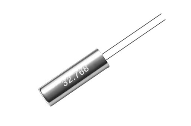
Parameter Reference Table
| Parameter | Fronter Quartz Piezoelectric Crystal Component Range | Design Consequence for an Industrial Oscillator |
|---|---|---|
| Nominal Frequency | 1 MHz to 96 MHz | Sets which clock roles the part can serve, from RTC to high-speed interface timing |
| Load Capacitance | 4 pF to 33 pF | Must be fixed before ordering; a mismatch produces a repeatable frequency offset |
| Frequency Tolerance | ±5 ppm to ±100 ppm | Consumes part of the total error budget at reference conditions |
| Frequency Stability | ±10 ppm to ±100 ppm | Determines whether the clock holds across cabinet temperature swings |
| Operating Temperature | -55 °C to +125 °C | Defines the environmental envelope the circuit must be validated against |
| Construction Material | Metal cover, ceramic base, quartz wafer | Affects thermal behavior, sealing and long-term stability |
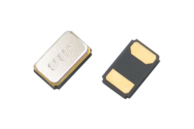
Step-by-Step Breakdown: Matching Crystal Parameters to an Oscillator Circuit
The sequence below is the order that avoids rework. Each step produces a decision that constrains the next one.
Step 1 — Fix the environmental envelope first
Establish the real temperature range the PCB will see inside the enclosure, not the ambient range of the room. Then select the stability grade that covers it. For Fronter's SMD oscillator series, that means choosing between the ±20 ppm window at -20 °C to +70 °C and the ±25 ppm window at -40 °C to +85 °C. If the cabinet is unventilated or the board sits near a drive stage, the wider window is the honest starting point.
Step 2 — Lock the load capacitance before the circuit is finalized
Decide the load capacitance the oscillator circuit will present, then specify the crystal unit against that same value. Fronter's crystal range spans 4 pF to 33 pF, which covers most common oscillator topologies. Changing load capacitance after the crystal is ordered converts a clean design into a frequency-offset problem.
Step 3 — Check ESR against available negative resistance
Compare the crystal unit's equivalent series resistance with the negative resistance the oscillator circuit can supply. The rule of thumb in oscillator design is to keep a comfortable margin so that start-up is reliable at the cold end, where ESR behavior is least forgiving. If margin is thin, either move to a lower-ESR crystal unit family or increase the drive capability of the circuit — not both at once.
Step 4 — Separate tolerance, stability and aging in the error budget
List frequency tolerance, frequency stability over the operating temperature range, and any aging allowance as separate line items. Fronter's crystal units are specified from ±5 ppm to ±100 ppm tolerance and ±10 ppm to ±100 ppm stability; treating those two numbers as one figure is the most common cause of an optimistic budget. Add load-capacitance pulling error as its own line as well.
Step 5 — Validate the parameters in production, not only in the prototype
Once the design is fixed, the parameters have to survive volume. Fronter applies 100% testing to its crystal products and offers ODM customization of parameters and appearance, with a monthly capacity of 80KK and a MOQ of 1000 pcs. For industrial buyers, that combination matters more than a single datasheet headline: the same parameter set has to be reproducible across every batch shipped.
Use Cases: Where These Parameters Decide Project Outcomes
Smart metering
An India-based smart meter manufacturer has used Fronter crystal components for ten years, with a cumulative volume of 5,000,000 units in smart meter applications resulting in stable operation. The project required fast delivery within 3–4 weeks and flexible customization to meet project-specific packaging and frequency requirements — a case where load capacitance, frequency tolerance and packaging had to be coordinated together rather than selected from a catalog at the end of development.
Smart home and communication electronics
Applications in smart home appliances, communication electronics and Bluetooth devices share one requirement: providing a stable clock signal for the IC. In these designs, the crystal unit works into an oscillator circuit under vibration and, in some configurations, high-temperature conditions. Deployments of this type have covered markets including Germany, Russia, India, Canada, France, Italy, Spain and South Korea, across project types such as mobile devices, Bluetooth headsets, smart air conditioners and security cameras.
Automated manufacturing equipment
On an automated line, the clock feeds controllers, sensors and communication interfaces at once. A stability shortfall that would be invisible in a consumer device becomes a synchronization error across the line. This is the setting where the -40 °C to +85 °C window and an explicit ESR margin stop being optional specification details.
Manufacturing capability behind the parameters: Fronter Electronics Co., Ltd operates a 21,000 m² facility with 286 employees, 19 R&D engineers, and annual output of 300,000,000 units. Approximately 70% of production is exported, with the EU and USA as principal markets. The company offers ODM production with customization of parameters and appearance, a lead time of 30–45 days, and remote after-sales support.
Comparison: Selecting by Parameter Priority, Not by Product Name
Crystal units and oscillators are often compared by product family. In industrial design, the more useful comparison is by parameter priority, because the same family can be specified several ways.
| Design Priority | Parameter to Fix First | Typical Fronter Configuration | Trade-off to Accept |
|---|---|---|---|
| Board space constrained | Package size | OSC-SMD2016 at 2.0 × 1.6 mm | Less thermal mass; validate stability at the hot end |
| General industrial control | Stability over temperature | OSC-SMD3225 at 3.2 × 2.5 mm | Mid-size footprint on the PCB |
| Harsh or unventilated enclosure | Operating temperature range | OSC-SMD5032 at 5.0 × 3.2 mm, ±25 ppm at -40 °C to +85 °C | Larger footprint; confirm board layout early |
| Low-power clocking | Supply voltage | 1.8 V to 3.3 V operation | Must verify logic-level compatibility of the driven IC |
| Real-time clock function | Nominal frequency | 32.768 kHz | Separate MHz clock still required for the main controller |
Two external benchmarks help frame where this sits in the market. TCXO products accounted for a 30% share of the crystal oscillator market in 2024 according to Precedence Research, reflecting demand for compensated stability in telecom and GPS roles. At the high end, the OCXO segment is projected by MarketsandMarkets to reach USD 528 million by 2028 on 5G base station demand. Most Industry 4.0 control, metering and interface designs sit between those poles, where a correctly specified quartz crystal unit paired with a well-matched oscillator circuit meets the requirement without paying for compensation the application does not use.
FAQ
Which standards apply to quartz crystal oscillators used in industrial equipment?
IEC 60679-1 is the primary international standard specifying general requirements and test methods for quartz crystal controlled oscillators, and it is the reference that applies to general industrial timing components. Where the equipment is vehicle-mounted or safety-critical, the relevant qualification is different: automotive-grade crystal oscillators must comply with the AEC-Q200 stress test qualification issued by the Automotive Electronics Council for use in ADAS and safety-critical systems. Buyers should confirm which of the two frameworks applies to their end product before finalizing a specification, because the test regimes are not equivalent.
Can crystal unit parameters such as load capacitance and frequency tolerance be customized?
Yes. Fronter Electronics Co., Ltd operates in ODM mode with customization of parameters and appearance. The standard piezoelectric crystal component range covers nominal frequency from 1 MHz to 96 MHz, load capacitance from 4 pF to 33 pF, frequency tolerance from ±5 ppm to ±100 ppm, and frequency stability from ±10 ppm to ±100 ppm across an operating temperature range of -55 °C to +125 °C. Customization is applied against those parameter families, so the circuit designer can specify the load capacitance and tolerance the oscillator topology actually requires rather than adapting the circuit to an off-the-shelf value.
What order quantity and production capacity should a crystal oscillator project plan for?
Fronter's minimum order quantity for crystal products is 1000 pcs, and monthly production capacity is 80KK, supported by a 21,000 m² facility with 286 employees and 19 R&D engineers. Annual output reaches 300,000,000 units. For buyers, the practical implication is that prototype and pilot quantities sit well below the capacity ceiling, so the binding constraint is usually lead time and parameter confirmation rather than volume availability.
How are crystal parameters verified before a production order?
Verification depends on testing discipline rather than on sample paperwork alone. Fronter applies 100% testing to its crystal products, which means each unit is checked rather than sampled from a batch. Combined with ODM customization of parameters and appearance, this allows a design team to confirm that the load capacitance, frequency tolerance and stability specified on paper are the values actually delivered. Buyers evaluating any supplier of piezoelectric crystal components should ask the same question: is testing applied to every unit or to a sample of the batch?
What lead time should be expected for industrial crystal oscillator orders?
Fronter quotes a standard lead time of 30–45 days for crystal products, with remote after-sales support. Delivery performance in practice is visible in the company's smart meter project for an India-based manufacturer, where fast delivery was achieved within 3–4 weeks alongside flexible customization to project-specific packaging and frequency requirements, across a ten-year supply relationship and 5,000,000 units. Project teams planning an Industry 4.0 rollout should treat that range as the planning window and confirm the specific configuration early, since parameter customization is completed before production rather than after. To discuss a specific configuration, request a quote or the product catalog through chinafronter.com or contact sales@chinafronter.com.
Conclusion
In Industry 4.0 equipment, oscillator accuracy is a parameter-matching problem before it is a component problem. Load capacitance has to be fixed before the crystal is ordered. Equivalent series resistance has to be checked against the negative resistance the circuit can actually supply. Frequency tolerance and frequency stability have to be budgeted as separate line items rather than merged into one headline figure. Operating temperature range has to be set from the real thermal environment inside the enclosure, not from room ambient. Get those four decisions right and the oscillator holds; get them wrong and no amount of downstream filtering recovers the clock.
The reference ranges in this guide — nominal frequency from 1 MHz to 96 MHz, load capacitance from 4 pF to 33 pF, frequency tolerance from ±5 ppm to ±100 ppm, frequency stability from ±10 ppm to ±100 ppm, and an operating temperature range of -55 °C to +125 °C for quartz piezoelectric crystal components — describe what is available to design against. What determines the outcome is whether the circuit and the crystal were specified as one system.
Next Step for Your Timing Design
Fronter Electronics Co., Ltd has manufactured quartz crystal resonators and oscillators since 1991, with ODM customization of parameters and appearance, 100% testing, a 1000 pcs MOQ, and a 30–45 day lead time. If you are specifying crystal parameters for an automated manufacturing project, send your load capacitance, frequency tolerance and operating temperature requirements to sales@chinafronter.com or review the full specification set in the Fronter product catalog.
Have Questions or Need More Details?
Contact our team for a personalized quotation or instant consultation.
Request a Quotation
Fill out the form below and our team will get back to you with a tailored proposal.
WhatsApp Direct Chat
Prefer to chat in real-time? Message us on WhatsApp for instant assistance & quick answers.
- Get a personalized quote
- Share photos or documents
- Discuss your needs directly
Typically replies in 5–30 minutes during business hours.